Design Studio Dubai

Fire Rated Joinery Guide for Fit-Out Teams

Fire Rated Joinery Guide for Fit-Out Teams

A fire door can carry a valid rating and still fail to perform as intended when the surrounding joinery, frame interface, ironmongery, or service penetrations are detailed incorrectly. That is why a fire rated joinery guide must go beyond selecting a labeled door or fire-resistant board. For fit-out teams, the real task is to coordinate a complete tested assembly that can be fabricated, installed, inspected, and maintained without compromising the project’s design intent.

In hotels, villas, retail stores, cinemas, and commercial interiors, fire-rated joinery often sits where architectural ambition and code compliance meet. Feature wall paneling, reception counters, corridor doors, concealed frames, access panels, and cabinetry can all affect compartmentation. Clear shop drawings turn those sensitive interfaces into buildable details before they become costly site decisions.

What Fire-Rated Joinery Actually Covers

Fire-rated joinery is not a single material category. It describes joinery elements designed to resist fire for a specified period when used as part of an approved system. Depending on the project and applicable authority requirements, this may include fire doorsets, frames, wall linings, service access panels, glazed screens, timber cladding, and built-in cabinetry adjacent to rated barriers.

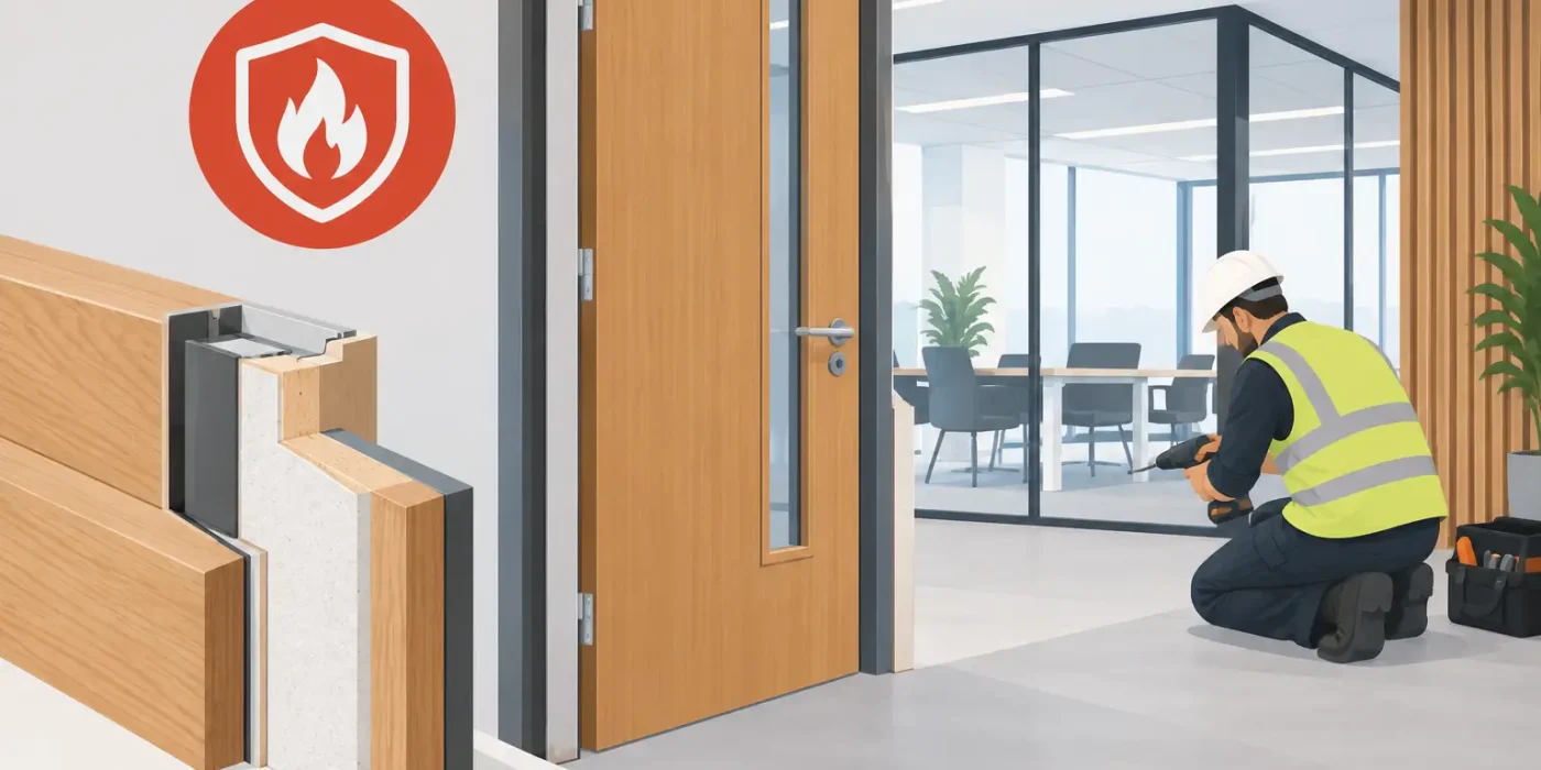
The rating applies to the tested configuration, not simply to individual products. A 60-minute door leaf, for example, does not automatically create a 60-minute doorset when paired with an untested frame, seal arrangement, hinge set, lock body, closer, vision panel, or wall construction. The same principle applies to decorative finishes. Adding veneer, laminate, grooves, acoustic treatment, or metal inlays may alter the assembly unless the system approval permits those modifications.

This distinction matters during fit-out procurement. Project teams should avoid specifying a fire rating in a finish schedule without identifying the required assembly, evidence of testing, and permitted design variations. A finish can be visually correct yet technically unacceptable if its thickness, adhesive, substrate, or fixing method falls outside the approved construction.

Start With the Fire Strategy, Not the Door Schedule

The fire strategy and approved architectural code drawings establish where rated construction is required, the required fire-resistance period, smoke-control needs, and the continuity of each compartment line. Joinery drawings should translate that information into fabrication and installation requirements.

Before detailing begins, the design, consultant, contractor, joinery manufacturer, and fire specialist need alignment on the governing standard and approval route. UAE and GCC projects may reference local civil defense requirements alongside international test standards and manufacturer certifications. The applicable requirement can vary by authority, building type, occupancy, and project specification. It should never be assumed from a previous project.

A coordinated review should establish whether each opening or element requires fire resistance only, fire and smoke performance, insulation performance, or a combination of these. It should also confirm the rating of the supporting wall, the required direction of door swing, escape hardware, clear opening dimensions, and whether the assembly needs acoustic, security, or accessibility performance. These requirements often compete for space within a slim frame profile or high-end decorative treatment, so resolving them early protects both program and cost.

The Details That Commonly Compromise Performance

Most fire-rated joinery issues occur at interfaces rather than in the center of a door leaf or panel. Shop drawings need to show those interfaces at a scale that installers and inspectors can use.

Frames, walls, and fixing zones

The frame must be compatible with the rated wall type and thickness. A masonry opening, drywall partition, shaft wall, and glazed screen system may each require different anchors, packers, gaps, and perimeter seals. If the wall is incomplete, uneven, or changed on site, the installer cannot simply fill voids with a convenient material. The approved perimeter detail must be followed.

Wall finishes create another frequent coordination point. Timber panels, stone, metal trims, and skirting must stop, return, or align with the frame in a way that does not interrupt intumescent seals, restrict door movement, or conceal an unapproved gap. Sections through the head, jamb, threshold, and adjacent cladding are more valuable than a general elevation alone.

Ironmongery and door hardware

Hinges, closers, locks, panic hardware, magnetic hold-open devices, viewers, kick plates, and access-control components can all affect a doorset rating. Hardware should be scheduled against the exact fire-rated doorset, not selected independently after the door has been approved.

Cutouts require particular care. A lock case, concealed closer, cable transfer, card reader, or vision panel reduces the material section of the leaf or frame. A tested system may allow specific hardware and reinforcements, but substitutions must be checked against the manufacturer’s certification. A visually similar item is not necessarily equivalent.

Seals, thresholds, and smoke control

Intumescent seals expand under heat to close gaps around an opening. Smoke seals may be required to limit smoke movement before temperatures rise enough to activate intumescent material. Their position, size, continuity, and compatibility with paint or veneer should be identified on the drawing and in the door schedule.

Thresholds deserve equal attention. A drop seal, threshold plate, carpet transition, stone sill, or floor finish build-up can affect the undercut and the ability of the door to close fully. Coordination with finished floor levels is essential, especially in hospitality corridors and public retail areas where flooring changes at door openings are common.

Services, access panels, and concealed joinery

Electrical boxes, data outlets, HVAC grilles, speakers, and inspection openings cannot be introduced into a rated lining without an approved solution. The issue is often missed when a feature wall is treated as a decorative package rather than part of a fire compartment.

Access panels should be specified as tested assemblies with the appropriate rating, hardware, and perimeter sealing. If cabinetry or wall paneling conceals a rated door or panel, the final arrangement must preserve access, door operation, signage, and inspection visibility where required. Concealment can support a refined interior, but it must not make a life-safety element impractical to use or maintain.

What a Fire-Rated Joinery Shop Drawing Should Show

A fabrication-ready drawing package removes uncertainty from a sensitive scope. It should identify the rated item, required performance period, tested system reference, wall type, frame profile, door construction, leaf thickness, seals, ironmongery, vision-panel details, finishes, and installation tolerances.

For complex interiors, the package should also include enlarged plans and sections showing adjacent ceiling, flooring, cladding, skirting, and services. A door schedule alone cannot communicate the relationship between a rated doorset and a full-height timber portal, curved wall finish, recessed base, or ceiling bulkhead.

Material callouts need to be specific enough for procurement and quality control. Rather than stating only “fire-rated MDF” or “fire-rated veneer,” drawings should define the approved substrate or system, thickness, finish build-up, edge treatment, adhesive where relevant, and limitations on site modification. This supports traceability when samples, submittals, and delivered materials are reviewed.

Design Studio LLC approaches this coordination as a construction-documentation task, not a drafting exercise. Detailed joinery sections and coordinated schedules help manufacturers understand what they are responsible for building, while site teams can verify how each assembly meets surrounding finishes and building elements.

A Practical Approval and Installation Workflow

Reliable delivery depends on sequencing. The fire-rating evidence should be reviewed before finalizing bespoke profiles, not after fabrication has started. First, confirm the fire strategy requirements and authority expectations. Next, select a suitable tested system that accommodates the intended architectural appearance and required hardware.

The joinery shop drawing can then incorporate the system limitations and coordinate the relevant trades. Manufacturer submittals, samples, hardware data, and test or certification documents should be checked as one package. If the project proposes a departure from the tested design, the team should obtain a formal technical assessment or approved alternative through the appropriate process rather than relying on verbal assurances.

At installation stage, the contractor should inspect openings, supporting walls, anchors, perimeter gaps, seal locations, hardware, and door operation before finishes conceal critical work. Site changes should be controlled through revised drawings and approved technical information. Cutting a new opening for a reader, changing a closer, removing a seal for easier closing, or trimming a leaf to suit an uneven floor can invalidate the intended performance.

Balancing Fire Compliance With Interior Design Intent

Fire-rated joinery does not require an ordinary-looking interior. Premium veneer, painted finishes, metal detailing, concealed frames, and coordinated wall paneling may all be achievable when they are developed within a suitable approved system. The trade-off is that design freedom is bounded by tested dimensions, materials, fixing methods, and hardware options.

Early technical coordination gives the team more choices. When the fire requirement is identified only after design sign-off, the usual result is a visible compromise, a costly redesign, or a procurement delay. When it is embedded in the joinery detailing stage, the rated assembly can be planned around the visual language of the project from the outset.

The most dependable approach is to treat every rated joinery element as a coordinated assembly with a documented path from design intent to site installation. That discipline gives project teams a clearer basis for approvals, fabrication, inspections, and long-term operation – while keeping life-safety requirements where they belong: built into the details, not left to chance on site.
When Are Joinery Drawings Required on a Project?

When Are Joinery Drawings Required on a Project?

A reception desk can look straightforward in a rendered elevation yet contain dozens of decisions that affect fabrication: panel build-ups, concealed supports, stone joints, access panels, lighting channels, hardware clearances, and fixing methods. That is why the question, when are joinery drawings required, should be addressed before materials are ordered or work begins on site.

For fit-out projects, joinery drawings are required whenever a built-in element must be manufactured, coordinated with other trades, or installed to a specific design and performance standard. They convert the design concept into dimensions, materials, construction details, and installation information that a joinery workshop and site team can act on with confidence.

When Are Joinery Drawings Required?

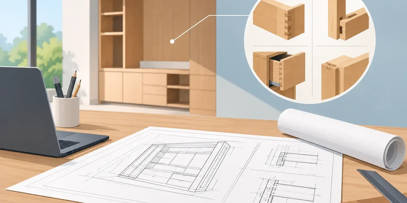
Joinery drawings are generally required for any custom-made interior component that cannot be safely or accurately delivered from a generic product specification. This includes reception counters, wardrobes, kitchens, vanity units, wall cladding, display shelving, bar counters, feature ceilings, doors, cinema wall systems, banquette seating, and integrated furniture.

They become especially necessary when the design includes multiple materials, concealed services, precise finish transitions, specialist hardware, or interfaces with flooring, ceilings, glazing, metalwork, lighting, and MEP systems. A dimension on an interior design layout is not enough to tell a fabricator how a unit should be built, supported, assembled, or fixed in place.

In practical terms, if an item is being priced, fabricated, approved, or installed as bespoke joinery, it should have a coordinated drawing package. The more visible, complex, high-value, or site-sensitive the element is, the greater the need for detailed documentation.

Design Drawings Are Not Fabrication Drawings

Concept drawings establish design intent. They communicate the general layout, visual character, material direction, and client experience. They are essential, but they do not usually provide every construction decision required by the workshop or installer.

Joinery shop drawings take the next step. They define the actual build-up of the item, including section details, panel thicknesses, carcass construction, edge treatments, hardware, access requirements, fixing locations, tolerances, and coordination dimensions. This is the information that allows project teams to verify whether the proposed design can be made and installed as intended.

For example, a design elevation may show a full-height timber feature wall with open display niches. A joinery drawing should clarify the substrate, module sizes, joint pattern, veneer direction, backing panels, lighting recesses, access provisions, and the relationship between the feature wall and adjacent doors or ceiling lines. Without these details, the contractor, manufacturer, and site team may each make different assumptions.

Project Stages That Need Joinery Drawings

The strongest time to prepare joinery drawings is after the design direction is sufficiently established but before fabrication release. Waiting until production has started often turns coordination into costly rework.

Before Final Tender or Procurement

At tender stage, outline joinery details can improve the accuracy of contractor and supplier pricing. A priced item described only as “custom timber counter” leaves room for broad interpretation. One bidder may allow for basic laminate construction, while another may include stone cladding, integrated lighting, drawers, metal trims, and concealed cable management.

Not every project needs a complete fabrication package before tender. However, key elevations, typical sections, material schedules, and clear scope boundaries help protect the budget and enable a more comparable commercial review.

Before Client, Consultant, or Operator Approval

For hotels, restaurants, retail stores, cinemas, and branded commercial interiors, shop drawings often form part of the formal approval process. Operators and designers may need to confirm appearance, durability, cleanability, brand alignment, accessibility, and maintenance access before production proceeds.

This is particularly relevant for front-of-house items. A mockup or 3D rendering may confirm the visual intent, but the joinery drawing confirms that the intended result can be fabricated within approved dimensions and material constraints.

Before Workshop Fabrication

No custom joinery should move into fabrication on the basis of an uncoordinated design sketch. Production drawings allow the workshop to prepare cutting lists, order materials, plan assembly, and identify technical conflicts before they become physical errors.

At this stage, the drawings should reflect approved finishes, verified dimensions, selected hardware, and current site conditions. If a finish, appliance, light fitting, or stone slab is still under review, that uncertainty should be clearly identified rather than hidden within an assumed detail.

Before Site Installation

Installation drawings are vital where units connect to finished surfaces or site-built elements. A millimeter-level discrepancy in a wall build-up, floor level, or ceiling height can affect the fit of full-height cabinets, cladding systems, counters, and doors.

Site measurement is therefore a critical part of the process. Drawings should be checked against actual openings and levels before manufacture, particularly in refurbishment projects, villas, and fast-track fit-outs where existing conditions can differ from early survey information.

Conditions That Make Detailed Drawings Essential

Some joinery packages can be relatively simple, but several conditions make detailed shop drawings non-negotiable. These include curved or irregular geometry, integrated appliances, concealed doors, fire-rated requirements, acoustic performance, stone or solid-surface interfaces, specialized ironmongery, and built-in lighting.

They are also essential where one item crosses trade boundaries. A bar counter, for example, may involve joinery, stone, stainless steel, plumbing, electrical power, data, refrigeration, and lighting. Without coordinated sections and service zones, each trade can complete its own scope correctly while still leaving an installation conflict at the point of assembly.

The same applies to retail display units and hotel guestroom furniture. These elements need to satisfy visual requirements while allowing for stock loading, maintenance, power access, cleaning, ventilation, and repeated use. A beautiful elevation alone does not resolve those operational demands.

What a Complete Joinery Drawing Set Should Clarify

The required level of detail depends on the project, but a fabrication-ready package should remove uncertainty for both the workshop and installation team. For major items, it should establish:

  • Overall plans, elevations, sections, and enlarged details.
  • Verified dimensions and clear reference levels.
  • Material types, thicknesses, finishes, grain direction, and edge treatments.
  • Hardware, accessories, appliances, lighting, and supplier-specific requirements.
  • Internal construction, support systems, fixing methods, and access panels.
  • Interfaces with adjacent finishes, glazing, metalwork, ceilings, floors, and MEP services.

A drawing set should also identify revisions clearly. On active projects, changing a cabinet width, finish code, or service location without formal revision control can result in outdated information reaching procurement or fabrication teams.

The Cost of Proceeding Without Shop Drawings

The argument against joinery drawings is often speed or cost. On a small, low-risk item using standard components, a simplified drawing may be sufficient. But eliminating documentation on a complex custom element rarely saves money. It transfers decisions from a controlled approval process to the workshop floor or site, where changes are more disruptive.

Common consequences include incorrect material orders, mismatched finish lines, insufficient clearances, inaccessible services, delayed approvals, inconsistent site workmanship, and disputes over what was included in the original scope. For hospitality and retail projects with fixed opening dates, even a minor joinery delay can affect multiple follow-on activities.

Detailed drawings also protect design intent. They give architects and interior designers a practical method to review whether the selected construction will preserve the proportions, material relationships, and visual quality established during design development.

How to Decide the Right Level of Detail

Not every project needs the same drawing depth. A standard laminate storage cabinet in a back-of-house room may require a concise plan, elevation, section, material note, and hardware specification. A lobby reception counter with curved stone, feature lighting, metal inlays, and integrated technology needs coordinated production details, material interfaces, and installation sequencing.

The right question is not whether drawings are needed at all. It is whether the available information allows a competent fabricator and installer to deliver the item without guessing. If the answer is no, the project needs further joinery documentation.

A specialist drafting partner can help establish a practical documentation scope based on the project stage, procurement route, and construction complexity. With a dedicated team of joinery and fit-out draughtsmen, Design Studio LLC develops accurate, coordinated shop drawings that support approvals, fabrication planning, and reliable on-site execution across hospitality, residential, retail, and commercial interiors.

The best time to resolve a joinery detail is while it is still a line on a drawing. Once it becomes a cut panel, ordered slab, or finished site installation, every unanswered question becomes more expensive to correct.

Shop Drawings vs Construction Drawings Explained

Shop Drawings vs Construction Drawings Explained

A hotel reception desk may look like a simple design feature in a rendering, but its successful delivery depends on hundreds of technical decisions: substrate thickness, stone joints, LED access, power locations, fixing methods, and site tolerances. That is where the distinction between shop drawings vs construction drawings becomes commercially significant. Both are essential project documents, but they answer different questions and carry different responsibilities.

For architects, interior designers, fit-out contractors, joinery manufacturers, and project managers, understanding the boundary between these drawing types prevents approval delays, rework, disputed scope, and costly site improvisation. The most reliable projects treat them as connected stages in one coordinated information process, not as interchangeable documents.

Shop Drawings vs Construction Drawings: The Core Difference

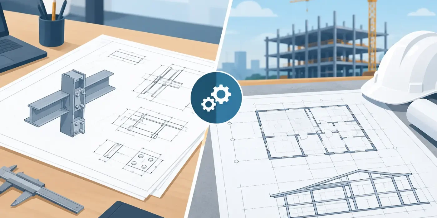
Construction drawings communicate the approved design and the requirements for building it. Shop drawings translate those requirements into the detailed information needed to fabricate, assemble, coordinate, and install a specific package of work.

Put simply, construction drawings establish what is to be built and where it belongs. Shop drawings establish how a trade will produce and install it.

Construction drawings are commonly prepared by the architect, interior designer, engineer, or appointed design consultant. They may include plans, elevations, sections, reflected ceiling plans, finish schedules, general details, specifications, and consultant information. Depending on the procurement route, they can support authority submissions, tender pricing, construction coordination, and issue-for-construction activities.

Shop drawings are normally prepared by, or on behalf of, the specialist contractor, fabricator, or supplier responsible for the work. In interior fit-out projects, that may include joinery, loose furniture, decorative metal, glass partitions, ceilings, wall cladding, stone, signage, lighting features, and specialist finishes.

The terminology can vary by contract and market. Some teams use “construction drawings” to describe the entire issued design package, while others use it only for approved issue-for-construction documents. The practical distinction remains the same: design documents define intent, while shop drawings develop trade-specific execution details.

What Construction Drawings Are Intended to Do

Construction drawings provide the project framework. They communicate the spatial layout, dimensions, design language, material selections, consultant requirements, and interface points that allow contractors to price and plan the work.

For a retail store, the construction package may show the overall floor plan, storefront elevation, fitting-room locations, ceiling concept, floor finish zones, wall finishes, and furniture placement. It tells the fit-out team where a cash counter, display wall, or feature bulkhead should be located. It may also identify key materials such as veneer, lacquered MDF, stainless steel, porcelain tile, or upholstery.

However, a construction drawing may not define every fabrication decision. A drawing can indicate a timber slat wall at a particular location without showing the precise slat module, concealed fixing rail, backing support, expansion allowance, edge treatment, or access panels required to build it safely and accurately. Those decisions belong in the shop drawing process, subject to the designer’s intent and project requirements.

Construction drawings are therefore not “less detailed” in a negative sense. They operate at the design and coordination level required for the project stage. Their effectiveness depends on clear intent, coordinated consultant information, complete schedules, and disciplined revision control.

What Shop Drawings Are Intended to Do

Shop drawings turn a design concept into a controlled work package. They identify exact dimensions, materials, thicknesses, joints, hardware, finishes, fabrication methods, fixing details, and installation references for a particular scope.

A joinery shop drawing for a villa wardrobe, for example, should go beyond a front elevation. It should show internal configurations, shutter sizes, carcass construction, shelf locations, drawer systems, ironmongery, veneer direction, edge details, skirting setbacks, LED channels, mirror or glass specifications, and interfaces with flooring, ceilings, and adjacent finishes.

This level of detail allows the manufacturer to order materials, prepare cutting lists, plan production, and verify that the item can be installed on site. It also gives the consultant and client a practical basis for review before fabrication begins.

Well-prepared shop drawings usually include drawing references, revision status, scale, room or zone references, clear dimensions, material callouts, detail sections, and notes identifying site-verification requirements. For complicated items, 3D views can help confirm the relationship between components, but they do not replace dimensioned technical drawings.

The Approval Process Does Not Remove Contractor Responsibility

Shop drawings are typically submitted for consultant, designer, client, or project-management review before fabrication. Approval confirms that the submission generally aligns with the intended design and coordinated project information. It does not automatically transfer responsibility for measurements, fabrication quality, safety, or installation performance to the reviewer.

This point matters particularly in fit-out work. A shop drawing may be approved with comments such as “verify on site,” “coordinate with MEP,” or “subject to material sample approval.” If the specialist proceeds without closing those comments, the approval stamp alone will not protect the project from avoidable errors.

A disciplined approval workflow should confirm that the latest architectural and engineering revisions have been incorporated, material samples are aligned with drawing notes, dimensions have been verified on site, and all relevant interfaces have been resolved. The drawing should then be issued to the workshop and site team under a controlled revision number.

Where Problems Usually Occur

The largest drawing failures rarely come from one missing dimension. They happen at interfaces between trades.

A ceiling feature may conflict with a sprinkler head. A stone counter may not accommodate the required power outlets. A wall panel system may cover an access panel. A reception desk may be detailed at the correct overall size but leave insufficient clearance for a wheelchair approach, a server rack, or maintenance access. These issues are expensive because they often appear after materials have been ordered or work has started on site.

Construction drawings identify many of these conditions, but shop drawings are where they must be resolved at component level. This is why shop drawing production should begin with coordination, not drafting alone. The drafter needs current architectural, interior, structural, MEP, and supplier information, along with a clear understanding of the intended sequence of installation.

For projects with custom joinery and layered finishes, site measurement is equally important. Existing conditions, slab variations, wall deviations, and completed MEP work can alter the available space. A fabrication-ready drawing that ignores verified site conditions can be precise on paper and wrong in reality.

How the Two Drawing Sets Work Together

The strongest workflow starts with a complete and coordinated design package. The specialist contractor then reviews the construction drawings, identifies missing information and clashes, raises technical queries where needed, and develops shop drawings for approval.

Once approved, the shop drawings guide procurement, fabrication, and installation. Any site change, consultant revision, or material substitution should trigger a controlled review of affected details. This avoids a common problem: the workshop fabricates from an old approved drawing while the site team works from a newer architectural revision.

The process is not linear on every project. Fast-track hospitality, retail, and commercial fit-out programs often require phased submissions so long-lead joinery or finish packages can move into production early. In those cases, teams need particularly clear drawing registers, revision tracking, and scope boundaries. Speed is valuable only when it does not create unpriced changes or uncoordinated fabrication.

What to Expect From a Fit-Out Shop Drawing Package

The required level of detail depends on the package, procurement scope, project complexity, and contract requirements. Still, a dependable interior fit-out shop drawing package should address the following five areas:

  • Accurate setting-out information tied to rooms, grids, walls, floors, and ceiling levels.
  • Fabrication details covering materials, thicknesses, profiles, joints, substrate, hardware, and finish direction.
  • Installation details covering fixings, tolerances, sequencing, access, and interfaces with adjacent trades.
  • Coordinated dimensions that have been checked against current drawings, site conditions, and MEP requirements.
  • Controlled revisions and clear status information so the workshop, approver, and site team use the same approved document.

For high-visibility spaces such as hotel lobbies, cinemas, restaurants, luxury villas, and flagship retail stores, these details directly influence perceived quality. Misaligned grain direction, inconsistent reveals, poorly located joints, and inaccessible service points can undermine even an excellent concept.

Choosing the Right Drafting Support

A drafting partner should understand more than drawing software. They should understand how a joinery detail is manufactured, how finishes behave at corners and transitions, where tolerances are needed, and how MEP services affect interior elements.

Design Studio LLC supports this process through a dedicated team of joinery and fit-out draughtsmen and coordinators who develop accurate, comprehensive technical documentation for UAE and GCC projects. The objective is practical: protect design intent while giving fabricators and site teams the information required for controlled execution.

Before releasing any specialist package, ask one useful question: could the workshop fabricate this item and could the installer set it out correctly without relying on assumptions? If the answer is no, the drawing has not yet done its job.

How to Avoid Ceiling Service Clashes Early

How to Avoid Ceiling Service Clashes Early

A reflected ceiling plan can look resolved at design stage and still fail on site when the sprinkler main occupies the same zone as a feature bulkhead, an access panel lands behind a decorative grille, or a large duct leaves no clearance for lighting. To avoid ceiling service clashes, project teams need more than a coordinated plan view. They need installation-ready information that tests services, finishes, maintenance access, structure, and ceiling geometry together before fabrication begins.

For hotels, retail spaces, restaurants, villas, offices, and cinemas, the ceiling is often the most congested construction zone. It carries mechanical, electrical, plumbing, fire protection, audiovisual, and security systems while also supporting the visual identity of the interior. A late clash does not only affect one trade. It can delay ceiling closure, require rework to joinery or gypsum details, compromise design intent, and create costly approval decisions under site pressure.

Why Ceiling Clashes Continue to Reach the Site

The primary issue is that each discipline may be working from technically valid information that has not been fully tested against the others. The MEP consultant may have allowed adequate duct size and service routes. The interior designer may have established a precise ceiling rhythm. The fit-out contractor may have allowed for buildability. Yet conflicts remain possible if those inputs are issued at different times, modeled at different levels of detail, or reviewed without a clear hierarchy.

Ceiling coordination becomes particularly sensitive where design elements are nonstandard. Curved gypsum profiles, coffered ceilings, shadow gaps, linear lighting, timber slats, decorative metal screens, acoustic rafts, and integrated HVAC grilles all reduce the available tolerance. A generic MEP layout cannot reliably resolve these conditions. The final ceiling zones, service depths, fixing methods, and visible interfaces must be coordinated around the actual approved detail.

There is also a practical distinction between a clash that is visible in a model and one that is genuinely buildable. A sprinkler pipe may clear a bulkhead by a few millimeters, but the installer still needs space for supports, fittings, insulation, testing, and access. Coordination must account for construction tolerances, not simply geometric overlap.

Start With a Ceiling Coordination Strategy

A strong process begins before detailed shop drawings are produced. The project team should define what takes priority in each ceiling zone. In a guestroom corridor, fire protection and maintainable services may govern the layout. In a luxury lobby, the architectural ceiling composition may set fixed visual lines that services must respect. In a cinema, acoustic performance and specialist equipment can drive the available ceiling volume.

This does not mean that one discipline always wins. It means the team makes informed decisions early, rather than allowing priorities to be decided by whoever reaches the site first. The agreed strategy should identify fixed elements, flexible elements, restricted zones, and areas that require a coordinated section rather than a plan-only solution.

Ceiling levels should also be established with care. Finished ceiling level is only one reference. Teams need to understand the structural soffit, bulkhead depth, service zones, hanger space, insulation thickness, and clear opening requirements for every major access point. Where the ceiling is stepped, sloped, or articulated, these dimensions need to be recorded in sections at the points where they change.

Use Coordinated Shop Drawings, Not Isolated Backgrounds

The most reliable way to avoid ceiling service clashes is to develop coordinated shop drawings from current architectural, interior, structural, and MEP inputs. These drawings should not merely overlay consultant backgrounds. They should translate the intended ceiling design into dimensions, levels, construction details, and trade interfaces that an installation team can act on.

A reflected ceiling plan should clearly locate lights, diffusers, sprinklers, detectors, speakers, cameras, access panels, curtain pockets, and ceiling-mounted equipment. However, plan coordination alone is not enough where services overlap vertically. Coordinated sections and enlarged details reveal whether a duct can pass above a feature ceiling, whether a light fitting has sufficient recess depth, and whether an access panel can be opened after adjacent joinery or services are installed.

For fit-out packages, the coordination drawing set should establish the relationship between visible finishes and hidden supports. This includes framing layouts, suspension points, gypsum board build-ups, metal or timber ceiling modules, and interfaces with wall cladding or joinery. When these items are left to site interpretation, services can be routed into locations that later prevent the intended ceiling system from being installed.

Coordinate the Elements That Are Commonly Missed

Major ducts and pipe mains receive attention because they are easy to see and difficult to move. Smaller components are often the source of the final site conflict. Their cumulative impact can be significant, especially in premium interiors where every ceiling element is exposed, aligned, or deliberately concealed.

The following items deserve specific review during fit-out coordination:

  • Access panels, including opening direction, clear maintenance space, finish integration, and alignment with ceiling modules.
  • Lighting drivers, transformers, control gear, and the heat or ventilation requirements associated with recessed fittings.
  • Flexible duct connections, diffuser plenums, pipe fittings, insulation, and service supports that extend beyond the nominal equipment footprint.
  • Fire alarm devices, speakers, sensors, cameras, Wi-Fi access points, and other low-current systems that compete for visible ceiling positions.
  • Curtain pockets, roller blinds, operable partitions, signage supports, and joinery fixing zones near the ceiling perimeter.

These components need not all be shown at the same graphic scale, but they must be accounted for in the coordination process. On a retail project, for example, a lighting track may look correctly centered until a sprinkler head, speaker, and smoke detector are added. The final arrangement must satisfy code requirements while preserving the visual order expected by the brand.

Resolve Access and Maintenance Before Ceiling Closure

A ceiling that looks clean on handover but cannot be maintained is not a successful installation. Access requirements should be reviewed with the operator, MEP contractor, and specialist suppliers before the final reflected ceiling plan is approved. Filters, dampers, valves, control modules, fan coil units, drivers, and fire-rated devices all require a defined maintenance approach.

In some locations, a discreet access panel is the appropriate solution. In others, the ceiling system itself may be removable, or a service route may need to be revised to reach a less visible area. The right answer depends on the ceiling finish, equipment type, authority requirements, operating model, and budget. Hiding every access point is rarely economical if it creates future maintenance risk.

The same principle applies to fire and life-safety systems. Decorative finishes must not obstruct sprinkler discharge patterns, detector coverage, or access for testing. Any change to device location should be verified through the responsible consultant and applicable authority process, rather than treated as a purely aesthetic adjustment.

Build in a Clear Review and Approval Sequence

Coordination is most effective when it follows a controlled sequence. First, confirm the approved interior design and architectural ceiling intent. Next, validate structural constraints and the latest coordinated MEP routes. Then issue detailed shop drawings, sections, and ceiling details for technical review. Only after comments are resolved should fabrication drawings, material orders, and site installation proceed.

This sequence matters because late changes have different cost consequences. Moving a diffuser on a drawing may take minutes. Moving it after a custom perforated metal ceiling, timber baffles, or gypsum bulkhead has been completed can affect several trades and the project schedule. A disciplined drawing register and revision process help ensure that site teams are building from approved information rather than superseded backgrounds.

Regular coordination workshops are particularly valuable on fast-track projects. The goal is not to create more meetings. It is to close specific issues with accountable decisions: confirm the final ceiling level, relocate a service, alter a bulkhead depth, revise an access solution, or obtain a required consultant approval. Each closed item should be reflected in the next issued drawing set.

Bring Fabrication Thinking Into the Design Detail

The difference between a well-drawn ceiling and a buildable ceiling is often found in the detail. A linear diffuser may need a specific plenum depth. A timber slat ceiling may require support rails at fixed centers. A decorative gypsum profile may need additional framing that conflicts with a proposed service route. These constraints should be evaluated before the ceiling is released for construction.

This is where specialist fit-out drafting delivers measurable value. Design Studio LLC prepares coordinated joinery and fit-out documentation that helps project teams test design intent against fabrication and installation conditions. With a dedicated technical team, the focus is not simply on producing drawings quickly, but on clarifying dimensions, material interfaces, and service coordination before they become site variations.

For complex interiors, 3D coordination and interior visualization can also support earlier decisions. They are especially useful for communicating ceiling composition to nontechnical stakeholders and checking whether visible devices disrupt a key design view. Still, the final construction decision should be supported by dimensioned shop drawings and sections, not by an image alone.

Treat Ceiling Coordination as a Delivery Control

Ceiling service coordination is not an administrative drawing exercise. It is a direct control on quality, cost, and program certainty. The earlier a project identifies restricted ceiling zones, confirms access requirements, and resolves trade interfaces, the less likely the team is to face rework after finishes are underway.

The most productive next step is to review the ceiling package before release and ask a practical question at every critical zone: can this be installed, inspected, maintained, and finished exactly as intended? When the answer is documented in coordinated drawings rather than assumed on site, the ceiling becomes a reliable part of project delivery instead of a source of late-stage disruption.

The Fit Out Shop Drawing Purpose Explained

The Fit Out Shop Drawing Purpose Explained

A hotel lobby reception counter can look resolved in a presentation set yet remain impossible to fabricate accurately without further technical definition. The fit out shop drawing purpose is to close that gap: converting approved design intent into coordinated information that joinery workshops, specialist suppliers, and site teams can build from with confidence.

For fit-out projects, this is not an administrative drawing exercise. Shop drawings are a delivery control document. They establish what will be made, from which materials, at what dimensions, how components meet, and how the finished work will be installed. When they are accurate and reviewed early, they protect design quality while reducing avoidable site decisions, rework, waste, and program pressure.

What Is the Fit Out Shop Drawing Purpose?

The primary purpose of a fit-out shop drawing is to translate a concept, tender package, or design development set into fabrication-ready and installation-ready documentation. Architectural and interior design drawings communicate the overall spatial vision. Shop drawings resolve the exact construction information needed to execute it.

This distinction matters because interior fit-out work involves many interfaces within limited spaces. A feature wall may need to coordinate timber veneer panels, shadow gaps, metal trims, concealed access doors, electrical points, lighting, fire alarm devices, and HVAC grilles. A ceiling detail may depend on sprinkler coverage, maintenance access, bulkhead framing, and reflected ceiling levels. Each interface requires decisions that cannot be left to assumption.

A coordinated shop drawing records those decisions before materials are ordered or work starts on site. It creates a common technical reference for the architect, interior designer, contractor, manufacturer, consultant, and client team. Rather than interpreting a visual intent independently, every party works from the same approved detail.

From Design Intent to Buildable Information

A strong shop drawing package does more than add dimensions to a design layout. It tests whether the design can be built within the actual conditions of the project.

For joinery, this typically includes plans, elevations, sections, enlarged details, material callouts, hardware references, edge treatments, fixing methods, and component dimensions. It should identify visible finishes and concealed construction where both affect quality, durability, access, or installation sequencing. A wardrobe elevation, for example, may show the external finish, but the fabrication drawings must also resolve carcass material, shelf positions, hanging rails, drawer mechanisms, door clearances, ventilation provisions, and wall fixing requirements.

For broader fit-out scopes, shop drawings coordinate partitions, ceilings, flooring transitions, decorative cladding, reception counters, wall features, loose and fixed furniture interfaces, signage, and specialist packages. The level of detail depends on the scope and procurement route. A standard office partition may require less development than a five-star hotel suite headboard wall with integrated lighting, upholstered panels, bedside controls, and concealed service access.

The goal is not to over-document simple work. It is to provide the right level of information for reliable fabrication, approval, and installation. Excessive detailing can slow a fast-moving project, while insufficient detailing transfers risk to the workshop and site team. The appropriate balance depends on design complexity, material sensitivity, tolerances, and the number of trades involved.

Why Shop Drawings Protect Cost and Schedule

Most costly fit-out issues begin as small unresolved questions. Is the wall finish measured from the structural wall or the finished face? Does the countertop depth allow for plumbing clearances? Can the access panel open after the decorative screen is installed? Does the selected stone slab accommodate the required panel size without an unwanted joint?

If these questions are addressed during shop drawing production, the project team can make informed choices while changes are still controlled. If they arise after fabrication or installation, the same decisions can result in material replacement, disrupted sequencing, extended labor, and compromised finishes.

Accurate drawings also support procurement. They allow contractors and manufacturers to verify quantities, order suitable materials, assess lead times, and plan workshop production. This is particularly valuable for hospitality, retail, and commercial projects where opening dates are fixed and several packages must arrive in sequence.

Dimensions are only one part of this control. Material specifications are equally important. A drawing should clearly distinguish between painted MDF, natural veneer, laminate, solid surface, stone, glass, metal, upholstery, and other finishes that may appear visually similar in a rendering. It should also identify grain direction, panel joint locations, finish codes, thicknesses, and any required mockups or samples. These details help maintain consistency across rooms, floors, or multiple retail locations.

Coordination Is the Real Value of Fit-Out Shop Drawings

Fit-out drawing quality is measured by how well it manages interfaces. A well-drafted ceiling plan must work with mechanical, electrical, plumbing, fire protection, audiovisual, and lighting requirements. A joinery detail must account for the wall build-up behind it, the floor level below it, and the services it conceals.

This requires disciplined coordination against the latest available consultant and site information. Existing-condition surveys, structural drawings, MEP layouts, equipment schedules, and approved material selections all influence the final detail. Where information conflicts, the drafting team should identify the issue clearly and raise it for resolution, not conceal it through assumptions.

Clash detection is often discussed as a software function, but effective coordination also relies on technical judgment. A model may identify overlapping geometry, yet it cannot always determine whether a ceiling access panel is practical to use, whether a joinery joint will align with a visual module, or whether maintenance space is sufficient for the equipment behind a decorative enclosure. These are execution decisions that experienced fit-out draughtsmen evaluate through detailed review.

At Design Studio LLC, this technical focus is supported by a dedicated team of 20 full-time joinery and fit-out draughtsmen and coordinators. Their role is to develop custom documentation that reflects the project design while addressing the practical demands of fabrication and site installation across UAE and GCC projects.

The Approval Process Should Reduce Risk, Not Create Delay

Shop drawings are commonly submitted for consultant, designer, contractor, and client review. That approval process is valuable when the package is complete enough for reviewers to assess the real outcome. A general elevation with limited construction data may obtain a visual approval but still leave significant fabrication risk unresolved.

A useful submission clearly identifies the drawing scope, revision status, dimensions, materials, and outstanding coordination points. Review comments should be tracked, incorporated, and issued through controlled revisions so that the workshop and site team are not working from superseded information.

Approval does not remove the need for site verification. Existing buildings, especially renovation projects and operational hospitality assets, often contain deviations from record drawings. Critical dimensions should be verified before fabrication, particularly for stone, glass, full-height joinery, curved work, and components that connect to existing finishes. Shop drawings provide the technical baseline; site measurements confirm that the baseline matches reality.

What a Reliable Shop Drawing Set Should Clarify

The most effective packages answer the questions that fabricators and installers would otherwise need to ask under time pressure. For complex fit-out elements, the drawing set should clarify:

  • Overall and component dimensions, including finished levels and setting-out references
  • Materials, finishes, thicknesses, color codes, and visible joint locations
  • Sections and enlarged details at interfaces, corners, returns, and transitions
  • Hardware, fittings, fixing methods, access requirements, and movement clearances
  • Coordination with MEP services, structural elements, equipment, and adjacent trades
  • Revision history, approval status, and instructions for site verification where required

These requirements are not identical for every project. A luxury villa may require highly tailored joinery detailing and close material coordination. A retail rollout may prioritize repeatable modules, fast approvals, and consistent brand execution across locations. A cinema fit-out may place greater emphasis on acoustic assemblies, fire-rated details, seating interfaces, and specialist audiovisual coordination.

Better Drawings Create Better Site Decisions

The purpose of shop drawings is ultimately practical: to make the next decision on a project easier, clearer, and less risky. They give a joinery manufacturer enough certainty to produce components accurately. They give a site supervisor the information needed to set out and install work correctly. They give designers a final opportunity to safeguard key visual details before construction makes changes expensive.

For project managers and developers, that clarity supports more predictable cost and program control. For architects and interior designers, it protects the intended result. For contractors, it reduces the uncertainty that causes work to stop while answers are sought.

The best shop drawings do not merely document an interior after it has been designed. They actively prepare that interior to be built well, measured correctly, coordinated across trades, and delivered with fewer compromises when the site program is under pressure.

How to Coordinate Joinery Drawings for Fit-Outs

How to Coordinate Joinery Drawings for Fit-Outs

A reception desk can look fully resolved in a design presentation yet still create costly site queries if its stone upstand, concealed lighting, service access, and adjacent flooring are not coordinated in the shop drawings. That gap between visual intent and buildable information is where fit-out programs lose time. Knowing how to coordinate joinery drawings gives architects, contractors, manufacturers, and project managers a controlled process for turning an approved concept into fabrication-ready and installation-ready work.

For hotels, villas, retail stores, restaurants, offices, and cinemas, coordination is not simply a drawing review. It is the technical alignment of joinery with architecture, finishes, MEP services, structural conditions, specialist packages, and site tolerances. The goal is clear: every party should understand what is being made, where it sits, what it interfaces with, and how it will be installed before materials are ordered.

Start With a Controlled Information Base

Coordination begins with confirming the latest approved information. A joinery package should not be developed from an outdated reflected ceiling plan, an early interior layout, or a rendering that no longer reflects the selected materials. Establish a drawing register and identify the revision status of architectural plans, elevations, sections, finish schedules, MEP layouts, structural information, and client-approved design details.

The joinery coordinator should compare these documents before detailed drafting begins. Floor plans establish locations and extents. Elevations communicate the visual arrangement. Sections reveal heights, recesses, and construction build-ups. MEP drawings identify items that can affect cabinets, wall paneling, counters, and ceiling features, including power outlets, data points, access panels, drainage, sprinklers, diffusers, and fire alarm devices.

This review also exposes missing decisions early. A feature wall may be shown at 3,000 mm high on an interior elevation while the ceiling section indicates a bulkhead at 2,850 mm. A wardrobe may be dimensioned to a finished wall line without confirming the actual wall build-up. These are coordination matters, not drafting assumptions. They should be recorded and resolved through the project’s formal query process.

Set the Correct Datum, Levels, and Setting-Out Rules

Many joinery errors are not caused by poor craftsmanship. They begin with inconsistent reference points. Every drawing package needs a clear setting-out strategy based on agreed grid lines, finished floor level, wall faces, and ceiling levels.

Use finished floor level as the primary vertical datum unless the project specifies otherwise. Indicate all critical heights, such as plinths, counter tops, shelves, mirror centers, TV backing, wall panel joints, and ceiling interfaces. Where flooring is not yet installed, identify whether dimensions are taken from structural slab level or finished floor level. This distinction is especially important in bathrooms, kitchens, hospitality public areas, and retail environments with multiple floor finishes.

Horizontal dimensions also need a clear hierarchy. Dimension joinery from fixed construction points where possible, such as structural grids, masonry returns, or completed wall faces. Avoid chains of small dimensions that accumulate tolerance across a long elevation. On a retail feature wall or hotel corridor, a few millimeters of variation at each module can create a visibly misaligned final panel.

Coordinate Joinery Drawings With Every Interface

A well-coordinated joinery drawing does more than show cabinets and paneling. It defines the boundaries between trades. This is where experienced technical review protects both design intent and construction sequence.

Walls, Floors, and Ceilings

Confirm what the joinery is fixing to and what sits behind it. Wall paneling may require plywood backing, metal framing, fire-rated substrates, acoustic insulation, or a cavity for services. A tall wardrobe needs confirmation of ceiling clearance and any bulkhead condition. Reception counters and banquettes need accurate floor finish build-ups so their plinths, kick plates, and finished heights remain correct.

For ceiling-height joinery, show whether it stops below the ceiling, runs into a shadow gap, or is installed before a gypsum bulkhead is closed. The preferred detail depends on design intent, tolerance expectations, and installation responsibility. A tight joint can look refined, but it may be unsuitable where ceiling movement or uneven substrate conditions are expected.

MEP and Specialist Systems

MEP coordination is essential wherever joinery conceals or supports services. Drawings should locate power, USB charging, data outlets, switches, thermostats, access doors, ventilation grilles, plumbing connections, and equipment clearances. Do not rely on a general note stating that services are to be coordinated on site. The relevant opening, cutout, access zone, and fixing arrangement should be shown in the applicable plan, elevation, section, or detail.

A minibar cabinet, for example, may require ventilation, a dedicated electrical outlet, condensate management, and removable panels for maintenance. A cinema wall feature can involve acoustic treatment, speakers, cable routes, and equipment access. In these conditions, the joinery drawing must coordinate the installation logic, not only the finished appearance.

Materials, Finishes, and Hardware

Finish codes should match the approved finish schedule exactly. Identify veneer direction, laminate type, paint color, metal finish, stone thickness, glass specification, edge treatment, and grain alignment where these affect fabrication or appearance. A simple elevation may suggest continuous timber grain across doors and panels, but the shop drawing must confirm panel sizes, joints, and realistic material yield.

Hardware deserves the same attention. Include hinge types, drawer runners, handles, locks, sliding systems, LED profiles, access fittings, and soft-close requirements. Show handing and opening direction for doors, particularly where clearances, equipment doors, or adjacent furniture create conflicts. If the manufacturer proposes an alternative hardware system, review its load capacity, maintenance access, finish, and effect on the original detail before approval.

Detail the Build, Not Just the Appearance

Plans and elevations establish the overall arrangement, but sections and enlarged details make a joinery package usable in the workshop and on site. Each item should communicate material thicknesses, substrate, carcass construction, fixing method, tolerances, reveals, shadow gaps, edge treatments, and interfaces with neighboring finishes.

A drawing that labels a surface as “timber veneer” is incomplete if it does not show the supporting board, edge lipping, panel joint, fixing method, and relationship to the adjacent stone or metal. Likewise, a floating shelf needs a section that confirms whether it uses concealed brackets, a welded steel support, a timber cleat, or another system approved for the intended load.

Buildability should guide the detail. Consider transport dimensions, site access, lifting requirements, sequence of installation, and the ability to replace damaged components. A single full-height reception panel may appear cleaner than a jointed solution, but it may be impractical to fabricate, transport through a completed lobby, or install without risk. The best detail balances visual quality with safe, repeatable execution.

Use a Structured Review and Approval Process

Coordination improves when comments are captured, assigned, and closed systematically. Internal checks should verify dimensions, references, section cuts, finish codes, hardware, drawing consistency, and conflicts with other packages. A second technical reviewer is valuable for complex areas such as kitchens, bars, washrooms, feature ceilings, and integrated furniture.

External review should be equally disciplined. Issue drawings with clear revision numbers and a transmittal record. Separate design approvals from fabrication approvals when the project workflow requires it. A design approval may confirm appearance and layout, while fabrication approval confirms construction, materials, and interfaces. Treating these as the same milestone can expose the contractor and manufacturer to avoidable changes.

During review meetings, resolve decisions against the drawings rather than relying on verbal direction alone. Any agreed change should be incorporated into a revised drawing set with an identifiable revision cloud or change note. This creates accountability and gives the site team one reliable source of information.

Verify Site Conditions Before Release for Fabrication

No matter how complete the coordinated package appears, field verification remains essential. Existing villas, refurbishment projects, and fast-track commercial interiors frequently contain walls that are out of plumb, uneven slabs, unrecorded beams, or service locations that differ from design drawings. Site measurement should confirm critical opening sizes, finished levels, wall conditions, and service points before final fabrication release.

This does not mean every drawing must wait until the entire site is complete. The practical approach is to identify hold points. Standard carcasses may proceed from approved dimensions, while scribed fillers, stone templates, closing panels, and interface pieces are held until site verification. That approach protects the program without forcing a poor fit.

At Design Studio LLC, a dedicated team of joinery and fit-out draughtsmen coordinates these technical dependencies to help project teams move from design approval to reliable fabrication and installation. The value is not more drawing sheets for their own sake. It is clearer decisions, fewer trade clashes, and a package that supports controlled delivery.

Well-coordinated joinery drawings give the workshop confidence to fabricate and give the site team confidence to install. When every dimension, material, interface, and approval has a clear place in the package, design intent has a far better chance of arriving on site exactly as intended.

How to Verify Millwork Dimensions on Site

How to Verify Millwork Dimensions on Site

A reception desk that is 10 mm too wide, a wardrobe that meets an uneven slab, or a feature wall interrupted by an unrecorded service point can stop installation even when the approved shop drawing appears correct. Knowing how to verify millwork dimensions is therefore not simply a measuring exercise. It is a controlled coordination process that confirms the built condition matches the information released for fabrication.

For hotels, villas, retail spaces, restaurants, and commercial interiors, millwork often interfaces with finished floors, wall cladding, ceilings, glazing, MEP services, and loose furniture. Each interface can affect final sizing. A reliable verification process protects design intent while giving fabricators and site teams the information needed for accurate production and installation.

Start With the Right Dimension Authority

Before measuring, establish which document and condition govern the work. Architectural plans may show nominal room sizes, while reflected ceiling plans, structural drawings, MEP layouts, and approved finish details may introduce constraints not visible in one drawing set. The site condition is the final authority for dimensions that affect fabrication, but it must be reviewed against the latest coordinated documentation.

Confirm the drawing revision, approved material schedule, finish build-ups, and relevant site instructions before beginning the survey. Measuring against an outdated layout can create a perfectly documented error. This is particularly common when partition locations, floor finishes, or ceiling details have changed after the joinery package was issued.

The survey should also identify whether dimensions are taken to unfinished structure, finished surfaces, or a defined setting-out line. A cabinet against a tiled wall requires the finished wall face. A freestanding island may be set out from a grid line or a finished floor datum. State the reference clearly on the verification record so the drafter, manufacturer, and installer interpret the measurement in the same way.

How to Verify Millwork Dimensions: Establish Datums First

Millwork dimensions become dependable when they relate to fixed, repeatable reference points. Select control datums that are unlikely to move or change during remaining construction works. These may include structural grid lines, completed wall faces, finished floor level benchmarks, doorway centerlines, or approved ceiling levels.

Do not begin by measuring individual walls in isolation. First confirm the room’s overall geometry. Measure the width and depth at more than one location, check diagonal dimensions, and record any variation in squareness. A room that is 4,000 mm wide at floor level and 3,980 mm wide near the ceiling cannot receive a full-height cabinet designed from one dimension alone.

For vertical installations, verify floor level and wall plumb as carefully as plan dimensions. Use a laser level where appropriate to identify high and low points across the installation zone. Record ceiling level at each end of a run, especially for tall wardrobes, display units, wall paneling, and bulkhead-integrated joinery. The required clearance may differ considerably where slabs deflect or ceilings step.

Measure the Whole Interface, Not Only the Cabinet Opening

A millwork item rarely works independently. Its dimensions are affected by adjoining materials, access zones, hardware clearances, and services. During the site survey, capture the complete installation envelope rather than only the nominal opening width, height, and depth.

For example, a vanity unit requires more than the wall-to-wall measurement. The verification should include finished floor level, wall tile thickness, plumbing stub-out centers, drain position, mirror or backsplash height, countertop overhang, and access requirements for traps or valves. Similarly, a retail display wall may need confirmed locations for electrical boxes, data outlets, sprinkler heads, signage supports, and lighting drivers.

Check adjacent doors, shutters, drawers, and equipment in their operational positions. A wardrobe may fit physically but fail once a nearby door swing blocks access. A pantry unit can clash with appliance ventilation requirements. For hospitality projects, housekeeping access and maintenance zones deserve the same attention as visible design details.

When an item connects to another trade’s work, measure both the physical location and the tolerance available. A stone countertop, metal trim, glazed partition, or ceiling feature may have its own fabrication constraints. The millwork drawing should make the intended interface explicit rather than relying on installers to resolve it on site.

Account for Finish Build-Ups and Tolerances

Nominal construction dimensions are not finished dimensions. Wall plaster, tile adhesive, stone, carpet, vinyl, raised flooring, cladding systems, and ceiling finishes can each alter the available space. Verify whether these finishes are complete, partially complete, or still based on approved build-up information.

Where finishes are incomplete, do not assume standard thicknesses without confirmation. Obtain the approved detail or coordinate directly with the responsible trade. A 15 mm difference in wall build-up can affect filler panel widths, countertop alignment, and the visual centering of a feature unit.

Tolerance should be designed into the millwork rather than treated as an installation problem. Scribes, filler panels, adjustable legs, shadow gaps, removable cover panels, and site-cut end panels can accommodate realistic construction variation while maintaining a clean finished appearance. Their use depends on the design language and material selected. A continuous timber veneer grain or a symmetrical stone composition may limit where adjustment can be concealed, so these decisions must be made before fabrication.

Avoid applying one tolerance rule across every item. A concealed back panel may accept a larger adjustment than a visible metal reveal. High-precision retail displays and luxury villa joinery generally require tighter control, more detailed templates, and earlier site verification than basic utility cabinetry.

Verify Services Before Releasing for Fabrication

MEP coordination is one of the most frequent causes of millwork rework. Confirm the location, elevation, size, and access needs of every service that enters, passes through, or sits behind the joinery. This includes electrical outlets, switches, low-current systems, water supply, drainage, HVAC grilles, fire alarm devices, sprinkler pipework, and gas connections where applicable.

Measure service centers from the same established datums used for the joinery. A note stating that an outlet is near the left side is not enough for fabrication. The drawing should show a measurable relationship to finished floor level, wall face, and a fixed horizontal reference.

Where service positions are not yet installed, identify the coordination risk rather than issuing a blind cutout. A temporary hold point, oversized access panel, or coordinated setting-out drawing may be more cost-effective than rebuilding a finished cabinet after services are completed. For high-value feature joinery, physical templates or a joint site check with the MEP contractor can be justified.

Document Conditions So Others Can Build From Them

Good verification is only useful when the findings are communicated without ambiguity. Record each measurement on a marked-up plan, elevation, or survey sheet, supported by photographs that show the reference points. Photos should clarify conditions, not replace dimensioned information.

A practical verification record should identify the room or area, drawing revision, date, surveyor, measurement datum, finish status, and any site constraints. Where the condition differs from the approved drawing, clearly distinguish between the design dimension, the measured dimension, and the proposed response. This allows the project team to make a controlled decision instead of assuming the fabricator will absorb the difference.

For complex items, produce revised shop drawings that incorporate field-verified dimensions and issue them for review before fabrication. Revision clouds, coordination notes, and clear drawing status help prevent an older version from reaching the workshop. Design Studio LLC applies this discipline through coordinated joinery and fit-out documentation that gives project teams a clear basis for approval, production, and site execution.

Use a Hold-Point Process for Critical Items

Not every millwork component needs the same level of site verification. Standard loose units may be fabricated from approved drawings with normal allowances. Fixed, full-height, curved, stone-clad, or service-intensive items should pass through defined hold points before production.

A useful release sequence includes four checks:

  • Confirm the latest approved design and finish information.
  • Verify the physical site dimensions, levels, and adjoining conditions.
  • Resolve discrepancies with the designer, contractor, and relevant trades.
  • Issue a field-verified fabrication drawing with clear approval status.

This process may appear deliberate, but it is usually faster than reacting to a mismatch after delivery. The cost of a short site survey and drawing update is small compared with remanufacturing veneer panels, delaying a hotel room handover, or holding a retail opening because a cash-wrap counter cannot be installed.

Common Errors That Create Avoidable Rework

The most damaging errors are often simple. Measuring from an unfinished surface, omitting a tile or cladding thickness, assuming walls are square, or failing to check a ceiling level can undermine an otherwise detailed joinery package. Another common issue is recording dimensions without stating the datum, which leaves the workshop to interpret where measurements begin and end.

Teams also lose time when surveys are treated as a one-person activity with no coordination follow-up. If a discrepancy affects design, services, cost, or program, it needs a visible decision and an accountable owner. Site measurement should trigger coordination, not merely produce notes.

The strongest millwork packages combine accurate field data with practical fabrication judgment. They recognize which dimensions are fixed, which can be adjusted, and which require client or consultant approval before work proceeds.

Before the first board is cut, make sure the installation space has been measured as a real construction condition, not assumed from a plan. That disciplined step gives every downstream team a better chance to deliver the intended finish without compromise.

In House Versus Outsourced Drafting Decisions

In House Versus Outsourced Drafting Decisions

A hotel mock-up room is approved, the joinery package is due, and procurement needs confirmed dimensions before releasing materials. At that point, the question of in house versus outsourced drafting becomes a delivery decision, not an administrative one. The wrong model can create drawing bottlenecks, unclear interfaces, fabrication rework, and avoidable pressure on the site program.

For fit-out contractors, interior designers, joinery manufacturers, and developers, neither option is automatically better. The right approach depends on project volume, technical complexity, internal coordination capability, and the level of control required over approvals and production information.

In House Versus Outsourced Drafting: The Core Difference

In-house drafting places the technical drawing team within the contractor, design practice, or manufacturing operation. The team usually works closely with project managers, estimators, procurement staff, site engineers, and workshop personnel. This can support quick clarification when the organization has consistent workflows and sufficient specialized resources.

Outsourced drafting assigns drawing production to an external technical partner. A capable partner operates as an extension of the project team, converting design intent, site information, material selections, and consultant comments into coordinated shop drawings, cutting lists, elevations, sections, and installation details.

The distinction is not simply who produces the drawings. It is about how well technical information moves from concept to fabrication and installation. A drawing package must resolve dimensions, material build-ups, finishes, hardware, tolerances, service interfaces, and sequencing before those issues appear in the workshop or on site.

When an In-House Team Creates Value

An in-house drafting department can be highly effective for organizations with a stable pipeline of similar work, established technical standards, and direct access to fabrication or construction teams. Joinery manufacturers with repeatable product ranges, for example, may benefit from drafters who understand their machinery, preferred details, standard materials, and production constraints.

Physical proximity can also speed up small clarifications. A workshop manager may identify a machining limitation and discuss it immediately with the drafter. A site team can raise an issue, review marked-up drawings, and receive a revised detail without waiting for a formal external coordination cycle.

This model works best when capacity is genuinely available. A small internal team may manage routine villa packages or a limited number of retail rollouts successfully. The risk begins when multiple projects reach the approval and production stages at the same time. Drawing quality can decline when skilled drafters are pulled between urgent revisions, tender support, site queries, and new production packages.

In-house teams also require continued investment. Recruiting experienced joinery and fit-out drafters, maintaining software licenses, training staff, retaining technical knowledge, and covering absences are all real operating costs. These costs are justified when workload is predictable and the business can keep specialist resources fully utilized.

Where Outsourced Drafting Has an Advantage

Outsourced drafting is often the stronger option when project demand fluctuates, deadlines overlap, or the work requires deeper specialist capacity than an internal team can maintain. Hotels, luxury villas, restaurants, cinemas, and large retail environments can generate extensive joinery packages with hundreds of unique details. A single project may require coordination across millwork, stone, metal, glass, upholstery, lighting, MEP interfaces, and architectural finishes.

An external drafting partner provides scalable production capacity without requiring the contractor or designer to carry a full-time team sized for peak demand. This is particularly valuable when a project moves quickly from design approval into procurement and fabrication. Rather than delaying production while recruiting or overloading existing staff, the project team can add qualified technical resources when needed.

The commercial benefit is equally practical. Outsourcing can convert fixed staffing costs into project-based expenditure while giving the client access to a broader technical team. The saving should not come from reducing detail or review time. It should come from an efficient delivery model, repeatable quality processes, and the ability to allocate the right level of resource to the package.

For GCC projects, an offshore-enabled production model can offer this balance effectively. Design Studio LLC combines UAE-facing coordination with a 20-person full-time team of joinery and fit-out drafters and coordinators, supporting cost-conscious delivery without separating technical production from project accountability.

The Risks to Manage With Outsourcing

Outsourcing does not remove the need for strong project leadership. It changes the coordination structure. If the external team receives incomplete design information, unverified site dimensions, or inconsistent feedback, it can only produce drawings based on those inputs. A technically polished package can still be wrong if decisions were not captured clearly.

The most common concern is loss of control. In practice, control is protected through a defined workflow: agreed drawing standards, a clear responsibility matrix, submission schedules, revision protocols, a single source of current information, and named reviewers. The outsourced partner should understand who can approve dimensions, materials, finishes, and deviations before documents reach fabrication.

Another risk is treating drafting as a low-cost drafting exercise rather than a technical coordination function. Generic CAD capacity may be suitable for simple plans, but joinery and fit-out shop drawings require knowledge of fabrication logic, material thicknesses, edge details, hardware clearances, shadow gaps, access panels, and installation tolerances. The partner’s portfolio and technical review process matter more than drawing output volume alone.

A Practical Decision Framework

The decision should be based on project requirements rather than a preference for keeping every activity internal. Review these four questions before setting the drafting strategy:

  • Is internal capacity available at the exact time it is needed? Count approved projects, expected revision cycles, and the workload created by site queries, not just the number of drafters on the organization chart.
  • Does the project require specialist fit-out detailing? Bespoke reception desks, curved feature walls, integrated lighting, high-end veneer panels, hospitality guestroom furniture, and cinema interiors demand more than basic drafting support.
  • Can the team maintain a disciplined review process? Whether work is internal or external, drawings need structured checks before issue for approval, fabrication, and installation.
  • Is the workload stable enough to justify permanent resources? Continuous repeat work may support an in-house model. Seasonal demand, fast-track programs, or large one-off packages often favor outsourced capacity.

The answer may be a hybrid model rather than a strict choice. Many successful fit-out businesses retain a core internal technical team for client contact, design interpretation, and workshop coordination, while using an external partner to manage peak workloads, repetitive package production, or specialist detailing.

Quality Depends on Process, Not Location

A drafter sitting in the same office as the project manager does not automatically create better drawings. Likewise, a remote drafting team is not inherently difficult to manage. Quality comes from defined inputs, qualified technical judgment, layered checking, and timely communication.

A reliable shop drawing process begins with a complete design package and a clear scope. It then progresses through site verification, material and hardware confirmation, detailed drafting, internal quality review, client or consultant approval, revision control, and final issue for fabrication or installation. Each stage should have an owner and a deadline.

The strongest outsourced partners make their coordination visible. They identify missing information early, raise RFIs before assumptions become details, flag constructability concerns, and maintain revision records. This helps protect design intent while giving fabricators and site teams drawings they can build from with confidence.

Choose the Model That Protects the Program

For a predictable production environment with sustained workloads and established internal expertise, in-house drafting can provide close operational alignment. For complex, fast-moving, or variable-volume fit-out work, outsourced drafting can add the specialist capacity and commercial flexibility needed to keep approvals, procurement, and fabrication moving.

The key is to evaluate drafting as part of construction delivery. Select the model that gives your team enough technical depth, enough review capacity, and enough responsiveness to resolve details before they become site problems. When drawings are treated as a controlled bridge between design and execution, the project gains more than documents: it gains clearer decisions, better fabrication outcomes, and a more dependable path to installation.

Hotel Fitout Guide for Reliable Project Delivery

Hotel Fitout Guide for Reliable Project Delivery

A hotel room can look complete in a render and still fail on site because a bedside panel conflicts with an outlet, a minibar lacks ventilation, or a bathroom vanity cannot be installed within the available tolerance. This hotel fitout guide focuses on the technical decisions that turn hospitality design intent into an operational, durable, and installable property.

For developers, operators, designers, contractors, and joinery manufacturers, hotel fitout is not one procurement package. It is a tightly coordinated set of rooms, public areas, back-of-house spaces, building services, finishes, furniture, fixtures, and equipment. A missed detail can repeat across 100 keys, affecting cost, program, guest comfort, and maintenance long after handover.

Define the Hotel Fitout Scope Before Design Development

The first requirement is a clear scope that separates fixed fitout, loose furniture, specialist equipment, and base-build interfaces. This sounds straightforward, but unclear package boundaries regularly create gaps between the architect, interior designer, MEP contractor, specialist suppliers, and fitout team.

A typical hotel fitout scope includes reception counters, wall cladding, decorative ceilings, guestroom joinery, wardrobes, vanity units, bathroom accessories, doors, ironmongery, flooring, feature lighting supports, and public-area furniture coordination. It may also cover restaurant millwork, buffet counters, spa treatment rooms, meeting spaces, staff areas, and executive lounges. Each area has a different operational requirement, finish standard, and approval path.

The operator’s brand standards should be reviewed alongside the interior concept at the beginning. Brand standards may set requirements for room layouts, mattress clearances, accessible routes, lighting levels, minibar provisions, technology locations, fire-rated assemblies, and approved materials. If these requirements are checked only during submittals, the project team may be forced into costly revisions after fabrication has begun.

Build a Room-by-Room Technical Brief

A room data sheet is the practical control document for repeatable areas such as guestrooms, corridors, bathrooms, and meeting rooms. It should identify the room type, dimensions, finishes, fixed furniture, loose furniture interfaces, equipment, power and data requirements, lighting, accessories, and relevant elevations.

For guestrooms, the technical brief should resolve the bed wall, headboard, reading lights, switches, USB or charging outlets, bedside units, wardrobe interiors, luggage bench, desk, minibar, television panel, mirrors, curtains, and bathroom joinery. The objective is not simply to show each item. It is to establish how every item is fixed, powered, accessed, cleaned, repaired, and replaced.

Coordinate Shop Drawings Before Procurement

A hotel fitout succeeds when approved shop drawings become the single reliable reference for fabrication and installation. Design drawings communicate the concept. Shop drawings verify that the concept can be manufactured, coordinated with adjacent trades, and installed at the actual site condition.

For joinery and architectural fitout, a coordinated drawing package generally requires plans, reflected ceiling plans, floor finish plans, sections, interior elevations, joinery details, enlarged plans, material schedules, door schedules, and fixing details. The level of detail should match the construction risk. A simple painted wall may need limited information, while a feature wall containing timber veneer, metal trims, concealed access panels, lighting, speakers, and fire devices requires precise coordination.

Dimensions must be taken from established setting-out points rather than assumed wall faces. Site walls can vary, slabs can deflect, and MEP routes can occupy the space intended for concealed joinery. Early site verification and a clear survey process protect the fabrication schedule from avoidable rework.

Resolve MEP and Technology Interfaces

Many visible fitout problems originate in concealed coordination. Guestroom headboards are a common example. They may need electrical boxes, low-voltage controls, reading lights, data outlets, thermostat controls, emergency systems, and mounting support within a limited wall depth. Without coordinated elevations and sections, the result can be misaligned devices, inaccessible wiring, or last-minute cutting into finished panels.

The same principle applies to reception desks, bar counters, buffet stations, and meeting-room credenzas. These elements often contain power, data, drainage, ventilation, refrigeration, point-of-sale equipment, and AV connections. Confirm service routes, access doors, maintenance clearances, and load requirements before finalizing the joinery construction.

A useful coordination review asks four questions for every technical interface: What is behind the finish? Who installs it? Can it be accessed after handover? What happens if the component requires replacement? This discipline reduces conflict between trades and protects the quality of the completed space.

Select Materials for Hospitality Use, Not Just Appearance

Hotel interiors experience continuous use, frequent cleaning, luggage impact, moisture exposure, and intensive maintenance. Material selection must therefore balance visual intent with durability, fire performance, cleanability, replacement availability, lead time, and budget.

Natural veneer can deliver a refined guestroom experience, but it requires careful veneer matching, edge protection, finish testing, and a repair strategy. Laminates may provide greater consistency and impact resistance in high-turnover areas. Stone can create a premium reception or bathroom finish, although weight, joint layout, staining risk, and substrate tolerance need early review. In wet areas, waterproofing build-ups, tile setting-out, drainage falls, and movement joints must work together rather than being addressed by separate trades.

Mock-ups are particularly valuable for guestrooms and critical public areas. A full-scale mock-up allows the team to assess proportions, ergonomics, lighting, finish junctions, door swings, maintenance access, and workmanship before repeating the solution across the property. It is more cost-effective to revise one approved prototype than to correct dozens of completed rooms.

Plan the Fitout Program Around Dependencies

A hotel opening date is often fixed by commercial commitments, operator requirements, or seasonal demand. The fitout program should therefore be built around approvals, procurement, fabrication, delivery, installation, testing, and snagging rather than around a broad construction completion date.

Long-lead items can include decorative lighting, hardware, stone, specialized wallcoverings, custom metalwork, sanitary fittings, loose furniture, and imported finishes. Their selection and approval should be linked to a procurement schedule with realistic manufacturing and shipping allowances. Substitutions may protect the program, but they should be assessed for visual consistency, technical compliance, warranty coverage, and operator acceptance.

Installation sequencing also matters. Ceiling closures may depend on MEP testing. Wall cladding may need to wait for concealed services. Flooring protection must remain in place while overhead work continues. Joinery installation should be scheduled after wet trades have reached stable moisture conditions and after critical dimensional checks are complete.

Use Quality Control as a Construction Tool

Quality control is not limited to the final snag list. It begins with approved samples, material submittals, shop drawing reviews, prototypes, and inspection hold points. The most effective teams agree on acceptable workmanship before large-scale installation begins.

Site inspections should check alignment, level, plumb, joint consistency, finish direction, edge quality, fixing security, hardware operation, sealant lines, access-panel alignment, and protection of completed work. For guestrooms, inspections should also test the guest experience: Can the wardrobe open fully? Is the desk usable? Are switches reachable from the bed? Do bathroom doors and drawers clash? Are housekeeping and maintenance tasks practical?

Digital coordination supports this process when drawings, revisions, comments, and approvals are controlled carefully. Issuing outdated details to a fabricator can be as damaging as an inaccurate measurement. A clear revision register and defined approval responsibility keep the site team working from current information.

Design Studio LLC supports hotel teams with accurate, comprehensive joinery and fitout shop drawings that connect design intent with fabrication and installation requirements. Its dedicated technical team coordinates details across hotel guestrooms, public areas, and specialist spaces, helping project stakeholders make decisions before those decisions become site issues.

The Hotel Fitout Guide: Common Risks to Address Early

The recurring risks in hotel fitout are rarely mysterious. They are usually known conditions left unresolved until they affect cost or time. Address these issues during detailed coordination:

  • Repetitive guestroom details that have not been tested in a full-scale mock-up.
  • Incomplete MEP provisions inside headboards, reception counters, bars, vanity units, and feature walls.
  • Material selections without confirmed fire ratings, lead times, cleaning requirements, or replacement availability.
  • Joinery dimensions based on design assumptions instead of verified site measurements.
  • Unclear responsibility for interfaces between fitout, furniture, equipment, technology, and base-build works.
  • Late operator comments after drawings are released for fabrication.

Not every project needs the same level of drawing detail. A limited renovation with retained MEP systems has different demands from a new-build luxury hotel or a branded conversion. However, the more repetitive, customized, or service-intensive the interiors are, the more valuable detailed coordination becomes.

A well-executed hotel fitout is felt by guests as comfort, quality, and consistency. For the project team, it is created through disciplined documentation, early coordination, verified materials, and installation details that give every trade a clear path to build the approved design correctly.

Joinery Drafting Services Review for Fit-Out Teams

Joinery Drafting Services Review for Fit-Out Teams

A joinery drafting services review should begin where project risk is highest: at the point where an approved interior concept must become a fabricator’s instruction and an installer’s working reference. For hotels, villas, retail stores, restaurants, commercial offices, and cinemas, a visually strong design is not enough. If dimensions, materials, interfaces, and installation conditions are unclear, the result is usually rework, approval delays, wasted material, or avoidable site variations.

The right drafting partner does more than produce attractive drawing sheets. It converts design intent into coordinated, fabrication-ready information that can be checked, priced, manufactured, and installed with confidence. Reviewing that capability requires more than comparing drawing rates or turnaround promises. Decision-makers need to assess the technical depth behind the output and the provider’s ability to support the actual fit-out workflow.

What a Joinery Drafting Services Review Should Measure

A useful review examines whether a provider can reduce ambiguity across the chain of designer, consultant, contractor, joinery manufacturer, and site team. The central question is simple: will the drawings allow the right product to be made and installed correctly the first time?

This depends on the project type. A luxury villa may require highly resolved wardrobes, kitchens, vanity units, feature wall panels, and bespoke furniture. A hotel requires repeatable room-type packages alongside public-area joinery, back-of-house requirements, and strict coordination with services. Retail environments often have compressed programs, branded fixtures, changing product displays, and demanding finish standards. The drafting approach should respond to these conditions rather than apply a generic detail library.

A capable provider will also understand the difference between a design drawing and a shop drawing. Design drawings establish the visual and spatial direction. Shop drawings test that direction against site dimensions, manufacturing methods, materials, tolerances, hardware, and adjacent trades. When this distinction is not managed carefully, contractors inherit unanswered questions that should have been resolved before production.

Review the Technical Detail, Not Just the Presentation

Well-formatted sheets can create a positive first impression, but presentation alone does not prove technical quality. Ask to review representative drawing sets for comparable projects and inspect how the details communicate buildability.

Dimensions and levels

Dimensions should be complete, logical, and traceable. A joinery elevation without clear setting-out dimensions, reference levels, and overall extents leaves too much to interpretation. Review whether drawings identify finished floor levels, ceiling conditions, wall offsets, panel widths, door clearances, and installation tolerances where relevant.

For refurbishment work, the team should recognize that as-built conditions may differ from issued architectural drawings. A strong drafting process includes a clear route for site verification and controlled updates. No drawing package can eliminate every site issue, but it should make responsibilities and assumptions visible before fabrication begins.

Materials, finishes, and hardware

Material callouts need to be specific enough for procurement and manufacturing. The difference between natural veneer, laminate, lacquered MDF, solid timber, compact laminate, stone, metal, and upholstered panels affects edge treatments, substrate selection, fixing methods, lead times, and final appearance.

Review whether finish codes are coordinated with the interior design schedule and whether details address grain direction, joints, reveals, shadow gaps, edge banding, metal trims, and transitions between materials. Hardware should be identified with suitable clarity, including hinges, runners, locks, handles, magnetic catches, lift-up mechanisms, and access panels. When the schedule, elevation, section, and detail contradict one another, the installer is forced to make a decision that can affect cost and design quality.

Sections, details, and interfaces

The most valuable information is often found in the sections. Elevations show appearance; sections reveal how components are assembled, supported, fixed, and aligned. A drafting review should check whether details explain carcass construction, backing requirements, plinths, wall battens, hanging rails, countertop supports, ceiling interfaces, and access for maintenance.

Particular attention should be given to interfaces with MEP services, fire-rated assemblies, glazing, flooring, stonework, metalwork, and loose furniture. A reception desk may look straightforward in plan but become complex once power, data, lighting, ventilation, stone cladding, and cable access are considered. Providers should identify coordination points early rather than leave them for site teams to solve under pressure.

Assess Coordination and Approval Control

Shop drawings are part of a wider approval process, not an isolated production task. The drafting provider should have a disciplined method for receiving reference information, recording comments, issuing revisions, and maintaining drawing status. This protects the project team from working to superseded information.

Ask how the provider manages consultant comments and whether revisions are clouded, numbered, and supported by clear issue records. On larger fit-out packages, a small untracked change to a panel size, finish, or hardware specification can affect multiple rooms or repeated units. The review process must make those impacts visible.

Coordination quality also depends on communication. The most effective drafting teams raise focused queries with proposed solutions. For example, when a ceiling bulkhead conflicts with full-height cabinetry, a useful query explains the clash, identifies the affected detail, and presents workable options. It does not merely report a problem and wait for others to resolve it.

This is where technical collaboration becomes commercially valuable. Early clarification can prevent material orders based on outdated assumptions and reduce the likelihood of variations appearing after manufacturing has started.

Consider Capacity, Turnaround, and Project Familiarity

Turnaround matters in UAE and GCC fit-out delivery, where approvals, procurement, and site activities often run in parallel. However, speed without checking creates downstream risk. A service provider should demonstrate how it can scale drawing production while retaining a consistent checking standard.

Evaluate the size and specialization of the team, the availability of coordinators, and the process for internal quality review. A provider using a dedicated team of joinery and fit-out draftsmen is generally better positioned to handle drawing packages with repeated room types, phased handovers, and concurrent revisions than a general drafting resource with limited joinery exposure.

It is also reasonable to ask about file compatibility, drawing standards, naming conventions, and the ability to work from the project’s established templates. These practical details affect how easily the contractor, consultant, and manufacturer can review the package. The best technical output loses value if it is difficult to navigate or inconsistent with the project’s document-control system.

Design Studio LLC supports this requirement with a 20-person full-time joinery and fit-out drafting team, combining UAE and GCC project understanding with cost-effective technical production support. For clients, the benefit is not simply drawing capacity. It is a structured resource that can respond to package complexity while keeping attention on buildability and approval readiness.

Compare Value Beyond the Drawing Rate

A low per-sheet or per-hour rate can appear attractive, especially during tender and procurement. Yet drafting costs should be considered against the value of avoided rework, improved material planning, faster approvals, and clearer scope definition. One incomplete detail on a high-value feature wall, hotel room package, or retail fixture rollout can create costs far beyond the original drafting fee.

That does not mean the most expensive provider is automatically the best choice. The right level of service depends on the project stage, package complexity, program, and the technical capability already available within the contractor or manufacturer’s team. A simple, standard joinery package may need efficient production from established details. A bespoke hospitality or luxury residential project needs deeper coordination and more frequent technical engagement.

When comparing proposals, look at the defined deliverables. Confirm the expected number of plans, elevations, sections, enlarged details, material schedules, door schedules, hardware schedules, and revision rounds. Clarify who is responsible for site measurement, MEP coordination, consultant submission, and final manufacturing sign-off. Clear scope prevents a low initial price from becoming a series of unplanned extras.

Questions That Reveal a Reliable Partner

Before appointing a drafting provider, ask for evidence of comparable work and review the actual level of detail, not only selected renderings. Discuss how the team manages missing information, site discrepancies, consultant comments, and urgent revisions. Confirm the checking process before issue and identify the person responsible for coordinating technical queries.

It is equally useful to test their understanding of your production method. A joinery manufacturer may have preferred board thicknesses, hardware systems, CNC requirements, or installation practices. A drafting partner should be able to incorporate these standards while preserving the designer’s approved intent. This balance is essential: drawings must respect the visual concept while remaining practical for fabrication and installation.

A dependable joinery drafting service creates certainty before material is cut and before teams arrive on site. Select the partner that asks the right questions, records decisions clearly, and produces drawings that give every trade a common, construction-ready reference.